When a leak-free geosynthetics system is an absolute must, having a “water-tight” internal quality control system may not be enough. Despite thorough diligence in following installation and quality procedures to the letter, perforations can still occur and go unnoticed even by the most trained eye. In these cases, post-installation electric leak location testing is used to confirm a contiguous, leak-free system.
Damage Derailment
Damage can occur through a variety of interfaces with a geomembrane. Prior to installation, mechanical damage can happen during transportation. On-site, any time a geosynthetic is moved, there is potential for damage from the forks of the machinery responsible for the transferring, to nails on a neighboring pallet or sharp rocks on the ground where it is being stored.
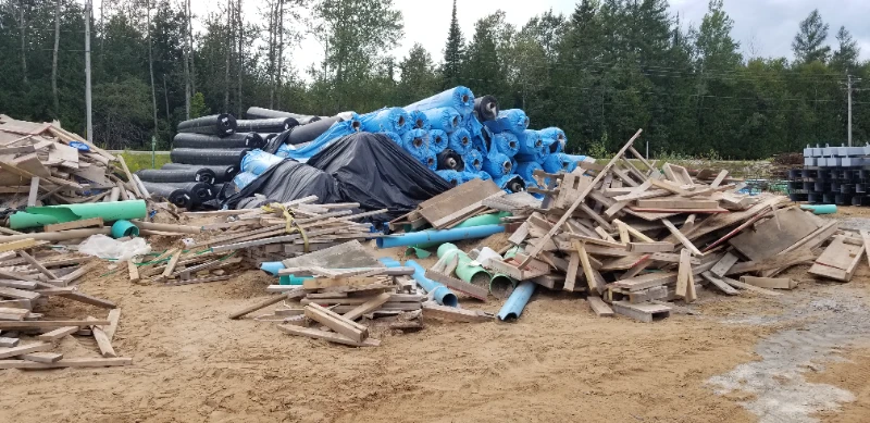 During deployment, poor preparation can leave rocks, sticks, or other debris in the subgrade. A simple snag from fragments during deployment can cause anything from pinholes to large gashes in the geomembrane. If the liner does not incur damage with debris left in the subgrade during the installation phase, the likelihood of penetration occurring after the containment is filled is greatly increased with additional pressure from the contents.
In the case of a soil covered geomembrane, the bulk of the damage that occurs is from placing the cover. Although many steps can be taken to minimize damage, there are always unknown objects capable of causing damage. No matter how careful someone is or what method of placement is being used, more than 95% of holes in geomembrane happen at this stage.
Whether deploying an entirely prefabricated membrane or performing all welding in the field, the quality of the welds will make or break the continuity of a lining system. Geomembrane systems fabricated in a factory have the advantages of a climate-controlled and clean environment. While this increases the likelihood of achieving high-quality welds, there is always the possibility of welding machinery or human error. Even the most stringent QA/QC protocols cannot effectively test every linear foot of welded seam in a project. In knowing all of the above variables, the option of having a lining system checked using electric leak location can help both the installer and owner sleep better at night.
Enter: Electricity
Electronic leak location testing systems have been used to locate damage in geomembrane lining systems for the last 40 years. The premise is to place a voltage across electrically insulated geomembranes. Next, the liner is scanned with a device that will detect the presence of electrical current. It is in these locations that a leak is present in the contiguous lining system.
Preparation prior to the execution of this type of leak location includes ensuring no metal is in contact with the liner during the testing. Metal pipe penetrations, batten strips, and anchor bolts are just some of the culprits that can cause electricity to flow through the liner. This could cause a masking of leak paths for the duration of the testing, resulting in damage being missed by survey equipment. Electrical leak location can be performed on geomembrane systems that are exposed, or those that are covered with water or soil with varying methods for achieving leak detection for each scenario.
Exposed to the Elements
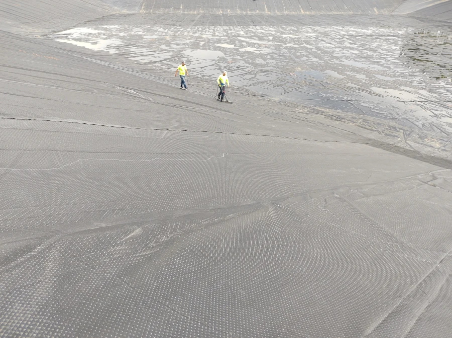
When performing leak detection on geomembranes that are dry, exposed, and in direct contact with the ground; the water puddle and water lance methods are employed. For this method, a cathode ground is placed in the soil, which serves as the electrically conductive layer. The anode is placed either in a water puddle created by a squeegee, or in the water stream of a lance. The water acts as the medium that finds the leaks, closing the electrical loop. This is indicated by either an audio signal or measuring the magnitude of the current created.
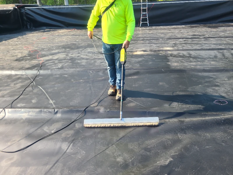
As with all systems, there are positives and negatives. The positives include the ability of this system to detect leaks as small as 0.04 inches. This is also the one electric leak location system that can be executed simultaneously during installation, decreasing the amount of time from installation to utilization of the basin. With a survey rate of over 5,000 sq ft per hour per operator, it is a rapid and effective way of detecting and repairing leaks prior to covering the liner with soil or end-contents.
Negatives of this system include ineffectiveness in locations where the geomembrane is not in contact with the ground. This can occur in the presence of wrinkles or waves in the liner. Steep slopes and the angles at the bottom of slopes can both decrease survey speed, as it can be difficult for the adequate amount of water to pool. Because this type of survey is dependent on water infiltration time, locations where repair patches are present also decrease survey efficiency. Stormy weather, a highly dry subgrade, and the inability to isolate or insulate conductive structures are all hinderances to using this type of leak location testing.
Eliminating Water Worries
Leak location testing isn’t only for geomembranes while they are still high and dry. Lining systems that are covered in liquid are similar to the process for those that are exposed. It begins with the same electrically conductive layer below the liner, normally the subgrade soil. A cathode is again placed in the subgrade, but in this case the anode is placed in the liquid contained by the geomembrane. A high voltage is then applied to the anode, creating an even voltage distribution throughout the liquid. Once both layers are electrified, a probe is used to detect abnormalities in the electrical paths caused by leaks in the lining system, where current is flowing through.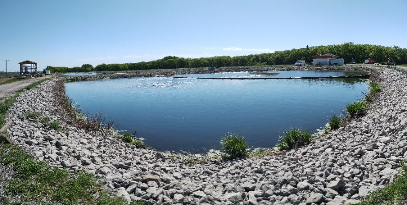
The primary advantage to this form of leak location testing is that it can be used to locate leaks within actively used ponds. There is an added benefit of increased inspection speed due to decreases in wrinkles and waves in the liner, and increased contact between the liner and conductive subgrade steep slopes and slope toes. Leaks smaller than 0.04 inches can be located with this type of survey, dependent on electric signal amplitude. Survey speed is dependent on the depth of the water and spacing between probe sweeps. If probe sweeps are closer than 1.3 feet of every point in the impoundment, then the survey rate is 8,500-10,500 sq feet per hour for two surveyors.
The main disadvantage to this method is that the survey cannot be done as the liner is being installed due to the requirement of flooding the entire membrane. The process is also lengthier as it requires filling the pond, conducting the survey, then draining the basin to repair any leaks located. In addition to the process taking longer, the liquid depth can be substantial depending on the pond design, negatively impacting speed. Lastly, large leaks may potentially interfere with the detection of smaller leaks near each other, impacting accuracy.
A Soil Covered Solution
Electronic leak location of geomembranes that are covered with soil post-installation, but prior to use, is like the above methods. An electrically conductive layer is required below the liner, and some moisture is required in the soil, but complete saturation is not necessary. Leak location can be accomplished in one of two ways. A dipole method with electrodes spaced equidistance apart during surveying, or by using one moving electrode referenced to a second, stationary electrode. Measurements are taken either in a grid, or at regular intervals on parallel lines. Survey results are then plotted to indicate anomalies that indicate leaks in the geomembrane under the soil layer.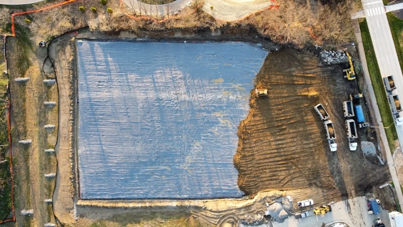
This method stands out as the best for geomembranes that will be covered with soil prior to employment, as damage can happen not only prior to and during liner installation, but also during soil deposition. Surveys can be completed during wet conditions and leaks as small as 0.12 inches can be located. The sampling density and how quickly the data is analyzed both determine the survey speed. If a data point is taken roughly every 10 square feet, the survey rate can range from 4,300 square feet to 10,700 square feet per person per hour.
Drawbacks to this method stem from the presence or absence of moisture within the cover soil. If void of wetness, the dry soil must either be scraped off, or water added to it for the survey to be completed. Another potential downside to this method, just as with liquid covered membrane surveys, large leaks can also mask the presence of smaller leaks in the same vicinity.
Electrically Embedded Geomembranes
Geomembranes themselves can now be electrically charged to assist in the detection of leaks. Polyethylene geomembranes can be manufactured with a layer of electrically conductive material. The liner itself can then be spark tested with the electrically charged layer facing the subgrade, and the non-conductive side facing the basin. A charge is given to the conductive layer, while an element is swept over the non-conductive top of the liner. This produces a spark where a closed circuit is present due to a leak in the system.
Benefits to this system include the elimination of non-consistent grounding due to the electrified element being part of the geomembrane itself. Due to the low current flow needed, this method can be completed during construction and both primary and secondary liners can be tested. Even more, concerns about dry soil are eliminated, and slopes can easily be tested as no water pumping is required. The rate of testing is dependent on the equipment, and ranges from 5,400 to 16,000 sq ft per man hour and detects leaks smaller than 1mm.
Although detecting an electrical charge due to inconsistent grounding is not an issue, the presence of steep slopes, waves and wrinkles in the liner is a detriment to survey speed. It cannot be completed during inclement weather and is also not an effective testing method if the liner is already covered with a protective layer of soil. This method cannot be used in place of traditional non-destructive seam testing as seams require a lower voltage and leak detection sensitivity than this system allows.
Perpetual Performance Monitoring
Some projects require continuous monitoring. For such occasions, a grid system has been developed using electrically conductive electrodes installed below a geomembrane. Potential measurements of electricity are then taken and processed to determine the location of any leaks.
Features of this type of system include the ability to conduct monitoring continuously, or at set intervals and operates with a protective soil layer and/or impounded liquid in place. Maximum areas of 100,000 square feet are suggested per monitoring station to detect the area of leaks.
Negatives of grid systems are that it cannot be conducted during construction of the project. The large amount of wire needed can also present a challenge while installing the system. Because of this, a significant area may have more than one system to service it. This system has the purpose of monitoring, and can give a general area of leaks, but not specific locations, necessitating larger excavations to be done for repair work if leaks are detected after the system has been put into use.
ICS has worked with all types of electronic leak location testing and can assist in connecting you to the best contractor to ensure that your project is sound. We hope to help you charge forward on your next project!
Sources
A GUIDE TO DETECT LEAKS ON INSTALLED GEOMEMBRANES; A. L. Rollin et al.